| Weight | 0.19 lbs |
|---|
Item # 39220-004
Previous product 
Item # 39212-004 Contact Us for Pricing and Orders Due to continuing supply chain issues and frequent price changes, please contact us directly at: Phone: 800-221-0714 or 732-291-3334 Dial extensions: 307 or 334 for pricing and delivery times and for placing orders.
Next product
Item # 39222-004 Contact Us for Pricing and Orders Due to continuing supply chain issues and frequent price changes, please contact us directly at: Phone: 800-221-0714 or 732-291-3334 Dial extensions: 307 or 334 for pricing and delivery times and for placing orders.
Close
Price Summary
- $100.54
- $100.54
- $100.54
In Stock
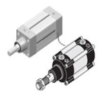
Highlights:
CompareSh.Stroke Cyl . D/A
Category: Pneumatic Cylinders
Additional information
Related Products
Recently Viewed


Item # 76024-71-58
Highlights:
Spool Design, In Line Mounting
Three position spool valves are used mostly to position cylinders. Valves with all ports open in the center position allow the cylinder piston rod to move freely, while valves with all ports closed in the center position will hold the cylinder in the desired position when no pilot pressure is present. A third type keeps line pressure on both sides of the cylinder piston.
Pneumatically actuated spool valves are available in 1/8 and 1/4 port sizes and require a minimum of 35 PSI operating pressure. Valves can be mounted with through body holes or assembled on manifolds.
Pilot port size (for actuation): 1/8 for all size valves.
Operating pressure range 35 to 145 PSI. Actuation force (pilot pressure): 35 PSI minimum.
Mounting via 4 through body holes 3/16? Dia.
For valve specifications see appendix. See accessory section for manifolds if required. For detail dimensions contact factory.
Item # 76420-02-10
Highlights:
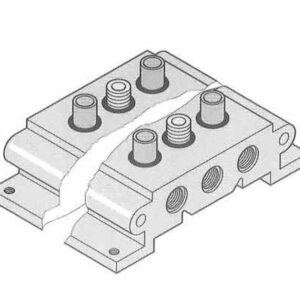
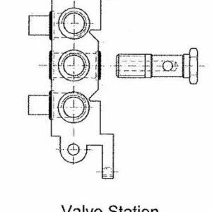
Two sizes of manifold kits are available (1/8 and 1/4 ported) for standard directional control valves, pneumatically or electrically operated (4 way, In-Line type, 2 or 3 position, except valve types 76123, 76124, 76127). Manifolds are single piece aluminum bases with common supply and exhaust ports on each end (1/8 or 1/4 metric respectively). For NPT supply ports, order supply line adaptor kit separately. Manifold kits include all valve mounting hardware, which accommodates both NPT, or Metric ported versions of valves. A hollow bolt is used to connect the valve to the base and supply the line air pressure. Two brass sleeves, sealed with O-rings, connect the exhaust ports. If a valve station is unoccupied (for future use), a blanking bar kit must be used to block manifold ports. Manifolds can be fastened down by 4 threaded M5 holes. Two or more 1/8 ported manifolds can be linked together with the use of connecting nipples and threaded tie rods (up to 3/16″ dia.) using the through body holes on the sides of the manifold to increase the number of stations.


Item # APM14-00
Highlights:
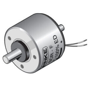
These pneumatic totalizers can be used as an event, part or lot counter. The counter registers pneumatic impulses on 4, 6 or 8 digit displays. Standard units operate with impulse pressures between 25 and 100 psi. Low pressure models operate between 7.5 and 30 psi. A variety of options include panel mounting with screws or mounting clips and surface mount with base or rear stud. The counters are available with or without manual reset.

Item # 76410-02-13
Highlights:
Standard coils fit all general purpose solenoid valves, except ISO valves with CNOMO air pilots. Coils are encapsulated to keep out water, oil and other contaminants providing splash proof protection when used with sockets below. The 3-prong plug includes a ground connection for the coil frame. Terminals can also be connected using crimp-on wire terminals with a 1/4″ spade dimension. Coil power consumption: AC (60Hz) is 3.5VA, DC is 2.5 W.
Item # 75043-25-41
Highlights:
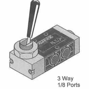
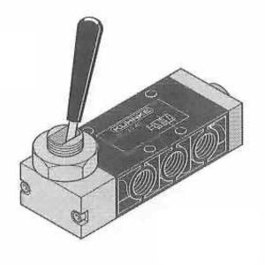
Lever valves can be used to manually switch air supplies on equipment or operate cylinders and other devices. Valves can be panel mounted or fastened to a surface via body mounting holes. Handles have a contemporary black molded grip and require 3.4 lbs. of force to operate. Valves are available in spring return, pneumatic return and maintained position versions.
Operating pressure range is 0-145 PSI. Actuation force at 90 PSI, is approx. 3.4 Lbs.
For normally open function on 3 way valves, reverse connect ports 1-3. For 2 way operation, plug port 3.
Panel mounting hole size for 1/8-ported valves is 5/8 inch diameter, for 1/4 ported valves, 7/8 inch. Through body mounting holes are 3/16″ dia.
Typical dimensions of 4 way 1/8 ported valves are 3.75″ L x 1.375″ W x 0.75″ D. For 1/4 ported valves: 4.75″ L x 2″ W x 1″ D. For 3 way valves subtract 0.75″ from L dimension. For pneumatic return valves add 1″ to L dimension. Allow space for fittings and tubing.
For valve specifications see appendix. For detail dimensions contact factory.