


| Type | Standard Timer |
| Timing Range | 3 to 100 hrs. |
| Operating Pressure Range | 0 to 145 psi |
| Control Pressure | 20 to 145 psi non-lubricated air |
| Output Valve | 4 way (5 ported) Cv – 0.13 Flow – 7 CFM at 100 psi Orifice size – 2mm |
| Connection | 10-32 (M5) ports |
| Media | Filtered air or gas. Non-lubricated. |
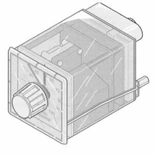
| Indicators | Displays set time and time remaining before valve actuation |
| Time Setting | Via front dial knob. Adjustable throughout timing range |
| Accuracy of Setting | ? 2% |
| Repeatability | ? 1% of end scale value |
| Operation | Independent regulated air motor. Air consumption 0.35 CFM. Output air piloted 4 way valve. |
| Reset | Automatic – by removal of control pressure. |
| Reset Time | 200 ms. |
| Timing Sequence | On delay or off delay depending on valve connections. |
| Operating Ambient | 0 to +60 ?C 32 to 140 ?F |
| Materials | Lexan Case Cast Aluminum Rear Housing Nylon, Brass Stainless Alloy Mechanism |
| Faceplate Dimensions | 2 13/16 in? |
| Behind Panel Depth | 4 3/8 in. |
| Behind Panel Height | 2 5/8 in. |
| Behind Panel Width | 2 5/8 in. |
| Panel Cutout | 2 5/8 in? |
| Mounting | Spring clips |
| Port Identification | Port 12 – Control input signal (on timer body). Valve 1 – System air supply 2 – Valve output “off delay connection” 3 – Exhaust for port 2 4 – Valve output “on delay connection” 5 – Exhaust for port 4 |
| Replacement Parts | Control port input filter 72754500-00 Output valve 54530 |
| Rotor Stop Option (Countdown on Hold) | A rotor stop option is available to override the timing action or to hold the timer valve in its switched position after the timer has completed its cycle, and signal pressure is removed. Option provides 2 additional rear ports connected via tube, which allows valves or other logic devices to be spliced into the internal circuit between the pilot signal regulator and rotor assembly. For holding timer valve in its switched position or to place “timing on hold”, an external 3 way valve (NO)can be used to block the flow to the air motor(connected between rotor stop ports 1-2). If timing on hold is desired, the pilot signal must remain on throughout the entire cycle. |
| Power Connections | For installations requiring larger valves, use the standard timer and connect a pneumatically operated single air piloted 3 or 4 way valve of the size required to the timer output. Contact factory with size requirements. |
| Typical Circuits | See typical timing circuit diagrams at the end of the timer catalog section for help in constructing pneumatic timer circuits. |
| Diagrams | Timer output valve is 4 way, 5 ported with 10-32 (M5) connections. Valves are supplied from factory blocked with a cap nut (port 4) for 3 way off delay. For on delay, move cap nut to port 2. For full 4 way operation remove nut. |
- CAD Drawings
There are no reviews yet.