| Weight | 0.25 lbs |
|---|
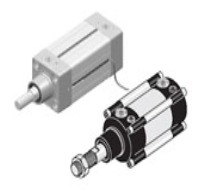
Item # 2629-080
Previous product 
Item # 2629-025 Contact Us for Pricing and Orders Due to continuing supply chain issues and frequent price changes, please contact us directly at: Phone: 800-221-0714 or 732-291-3334 Dial extensions: 307 or 334 for pricing and delivery times and for placing orders.
Next product
Item # 2629-160 Contact Us for Pricing and Orders Due to continuing supply chain issues and frequent price changes, please contact us directly at: Phone: 800-221-0714 or 732-291-3334 Dial extensions: 307 or 334 for pricing and delivery times and for placing orders.
Close
Price Summary
- $97.19
- $97.19
- $97.19
In Stock
Highlights:
CompareMin. Stainless Cyl. D/A Univ.
Category: Pneumatic Cylinders
Additional information
Related Products
Recently Viewed

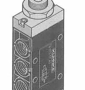
Item # 75022-66-23
Highlights:
Shroud Head prevents accidental operation. Button is (lush with shroud surface and the diameter is 1 1/8 inches. Operating force 14 ounces.
Operating pressure range is 35 to 145 PSI. Minimum operating pressure is 35 PSI. Actuation force at 90 PSI. is approx 14 ozs.
Panel mounting hole is 7/8 inch (22 mm) diameter. Above panel dimensions are 1.375″ Dia. x 1″ H. (Mushroom) or 0.625″ H. (Shroud Head).
Behind panel dimensions of 3 way valve – 3.75″ D x 1.375″ H x 0.75″ W; 4 way valve – 4.25″ D x 1.375″ H x 0.75″ W.
Allow space for fittings and tubing.
Valve through body mounting holes are 3/16″ diameter.
For valve specifications see appendix. For detail dimensions contact factory.

Item # PT41I
Highlights:
The PT timer is an adjustable precise time delay pneumatic device. The timer is available with an on delay (NC), or an off delay (NO) output. The timer has 1/8 inch NPT ports.
The PT series timer combines a pneumatic timing mechanism with a floating spool valve assembly to provide a wide range of adjustable time control for fluid power systems. The timing assembly, which operates independently of the control pressure, is available in nine different ranges from one tenth of a second to 60 minutes, adjustable by means of a time-calibrated dial. Timing action is initiated by a motor diaphragm operated by a control pressure of from 5 to 140 PSIG.
The timer is equipped with a multi purpose 3 way output valve allowing it to be used as normally open, normally closed or as a diverter.
The PT is designed for panel or surface mounting. Panel mounted versions include a 3 13/16 inch square bezel while surface mounted units are equipped with a bracket for vertical mounting. If required, The PT can be specially calibrated for mounting horizontally.
Off Delay Timer Operation Applying pilot pressure of at least 100ms in duration to the control port shifts the valve. When the pilot pressure is removed, the timing sequence begins. After the timer reaches its set time, the valve switches off. Re-applying the pilot pressure resets the timer and valve.
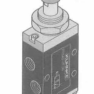
Item # 76023-34-41
Highlights:
One way roller lever operates valve only in one direction. Actuation force is 14 ounces and roller lever travel is approx. 5/32 inch (4mm).
Operating pressure range 35-145 PSI. Minimum pressure 35 PSI. Actuation force at 90 PSI, is approx. 14 ounces.
Approximate valve body dimensions for 1/8 ported valves are 2.75″ L (3 way), 3.5″ L (4 way) x 1.375″ H x .75″ W. Approximate valve body dimensions for 1/4 ported valves are 4.75″ L x 2″ H x 1″ W. Roller arm extends 1.81″ beyond body and travel is .156 in actuate direction and .5″ in non actuate direction. Through body mounting holes 3/16″.
For valve specifications see appendix. For detail dimensions contact factory.

Item # 51006-01US
Highlights:
The Series 51 timer is an adjustable precise time delay control device. The timer is available with either an on delay- (NC) or off delay- (NO) 3 way built-in valve. It is designed for mounting along with valves or other logic devices and is available with 10-32 (M5) bottom ports, or 1/8″ NPT side ports. Bottom ported timers can also be panel mounted using (2) threaded M3 inserts on the top cover.
Timing operation can be set up in 2 ways; either via direct connection of the pressure line to be timed (1/8″ NPT ported only) or via a separate pilot signal. When pressure is applied to the input (or pilot port) the timing sequence begins by setting a vacuum within the timer. Using atmospheric pressure (independent of line pressure), the timer begins the preset timing cycle. At the end of the cycle an internal 3 way valve is switched providing an output. The timer resets automatically after removal of the control signal.
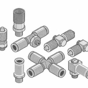
Item # 50500
Highlights:
Brass metric sized fittings provide a full family of connectors for most applications in miniature pneumatics. Machined from solid brass stock, fittings are dependable, easy to install and reduce space requirements.
Series 50 fittings also include quick connect couplings and brass manifolds.
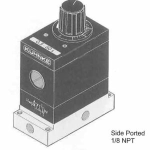
Item # 75042-27-21
Highlights:
Knob valves have a small travel of about 1/4 inch and can be easily operated with the palm of a hand. Knobs are constructed of sturdy black molded material. Available in spring return, pneumatic return and push-pull versions.
Operating pressure range is 0-145 PSI. Actuation force at 90 PSI: 1/8 port approx. 3.4 Lbs., 1/4 port 11.3 Lbs.
For normally open function on 3 way valves reverse connect ports 1-3. For 2 way operation, plug port 3. Panel mounting hole size for 1/8-ported valves is 5/8 inch diameter, for 1/4-ported valves, 7/8 inch. Above panel dimensions: 1/8-ported are 1″ Dia. x 1.5? H: 1/4-ported -1.5″ Dia. x 2.25″ H.
Typical behind panel dimensions of 4 way 1/8 ported valves are 2.5″ D x 1.375″ W x 0.75″ H; 1/4 ported valves- 4″ D x 2″ W x 1″ H. For 3 way valves subtract 0.75″ from depth. For pneumatic return add 1″ to depth dimension. Allow space for fittings and tubing.
For valve specifications see appendix. For detail dimensions contact factory.
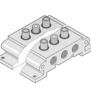
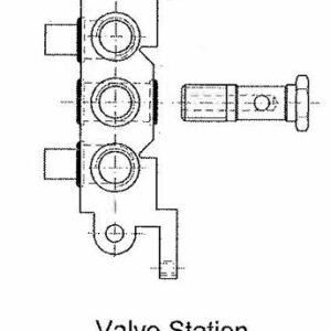
Item # 76440-02-02
Highlights:
Two sizes of manifold kits are available (1/8 and 1/4 ported) for standard directional control valves, pneumatically or electrically operated (4 way, In-Line type, 2 or 3 position, except valve types 76123, 76124, 76127). Manifolds are single piece aluminum bases with common supply and exhaust ports on each end (1/8 or 1/4 metric respectively). For NPT supply ports, order supply line adaptor kit separately. Manifold kits include all valve mounting hardware, which accommodates both NPT, or Metric ported versions of valves. A hollow bolt is used to connect the valve to the base and supply the line air pressure. Two brass sleeves, sealed with O-rings, connect the exhaust ports. If a valve station is unoccupied (for future use), a blanking bar kit must be used to block manifold ports. Manifolds can be fastened down by 4 threaded M5 holes. Two or more 1/8 ported manifolds can be linked together with the use of connecting nipples and threaded tie rods (up to 3/16″ dia.) using the through body holes on the sides of the manifold to increase the number of stations.