

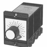

| Type | Panel Mount Horizontal Bezel |
| Timing Range | 6 to 60 sec. |
| Operating Pressure Range | 15 to 100 psi |
| Connections | 10-32 or 1/8 NPT ports via bottom sub plate |
| Control Pressure | (A) Low Press. – 15 to 100PSI (B) Standard – 30 to 100 psi |
| Media | Filtered air or non-aggressive gas, non-lubricated. |
| Timing Valve | Cv – 0.005 Flow at 100 psi -0.1 CFM |
| Dial Indicator | Displays set time |
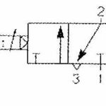
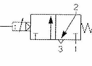
| Timing Start | Application of pilot pressure to control port |
| Reset | Automatic by removal of pilot signal. |
| Reset Time | 60 ms at 50 psi |
| Repeatability | ± 3% of selected time |
| Time Setting | Via Adjustment Knob Accuracy ±10% |
| Operation | Timing cycle uses atmospheric pressure drawn into vacuum. |
| Air Consumption | 0.1 CFM at 100 psi |
| Materials | Acetal and polycarbonate enclosure Diaphragms – Buna N |
| Operating Ambient | 0 to 65 ºC 32 to 150 ºF |
| Height | 2 1/16 in. |
| Width | 1 1/2 in. |
| Depth | 4 1/4 in. |
| Mounting | Via sub plate (2 holes) or if Panel mounted, through a 1 1/2″ square cutout. 2 mounting holes required, hardware included. |
| Low Pressure Version | The PMT standard control input pressure range is 30 to 100 PSI. For a low pressure pilot actuator (15 PSI min.), change the “B” in the catalog number to “A”. |
| Subplate Mounting Position | Standard timers are supplied with the subplatemounting position at the bottom of the timer. Formounting the subplate in another position, change thelast digit of the catalog number as follows: 1 for top; 2for right side; 3 for bottom; 4 for left side. |
| Power Connections | For installations requiring larger output valves, use thestandard timer and connect a pneumatically operatedsingle air piloted 3 or 4 way valve of the size required tothe timer output. Contact factory with sizerequirements. |
| Typical Circuits | See typical timing circuit diagrams at the end of the timer catalog section for help in constructing pneumatic timer circuits. |
There are no reviews yet.